Project omschrijving
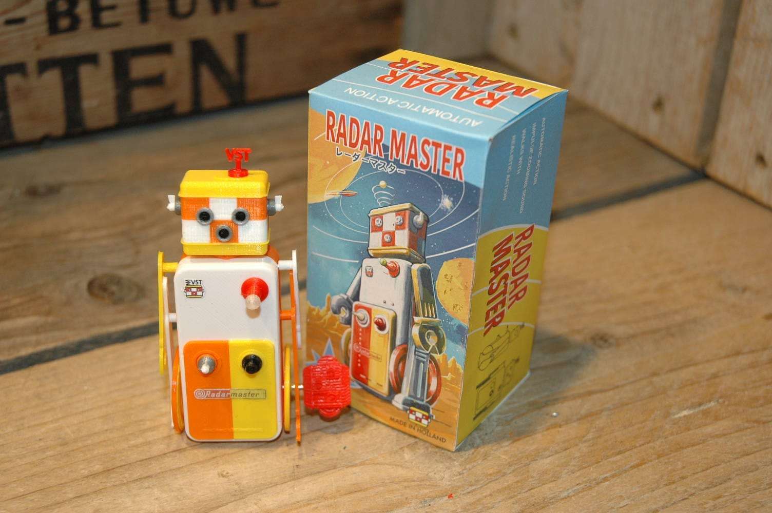
VST – Radar Master Robot Clockwork DIY Version with Original Box.
I made the complete design for this robot a couple of years ago. The ” original ” radar master robot, of which only 3 were build, was in fact a remote control unit from a German Arnold Boat. You can read ALL about this here: https://vintagespacetoys.com/products/vst-radar-master-robot-number-2-3/
After that i made a fully 3D printed, app remote controlled self balancing version:
https://vintagespacetoys.com/products/vst-radar-master-robot-3d-printed-self-balancing-robot/
As these were both very expensive projects and this robot became my VST Logo as well I thought it was about time to make a more affordable version. This one is a DIY ( Do It Yourself ) fully 3D printed version with a clockwork mechanism that makes the robot to go forward with vst charm 🙂
The robot is very small, only 9 CM in height. The challenge this time was to go as small as possible to find the edges of 3D printing , what is possible and what not anymore and… I first used the Ultimaker 3 to print parts in 2 colors.
I made this a DIY kit to cut down the complete shipping costs. Now shipping is FREE for this robot.
It comes as as DIY Kit that is easy to build together. It will take about 45 – 60minutes to complete the robot and the box.
The robot will be shipped in a flat envelope and comes as a DIY kit with all the parts you need and glue to build the robot. Here below you find the user manual, the building instructions and over 80 pictures to help you build up this robot.
The pictures show a small selection of the 80 pictures you will find in the download. These pictures will guide you step by step through the building process.
The price is 49 USD including free shipping worldwide.
I have made many more 3D Printed Parts and Toys over the years. Looking for something ? Feel free to contact me on: boogo.nl@gmail.com and .. if I don’t have it.. perhaps I can make it for you 🙂
Marco
Marco
User Manual and Building Instructions
General:
* all the parts that need to be glued together need some very light sanding first to assure a perfect fit.
* Let all the parts dry properly for about 10 minutes.
* Replacement parts ( in case you make a mistake ) are available 🙂 !
* For Questions email me: boogo.nl@gmail.com
* Here you can dowload the Zip File with the pictures that will help you through the building process: DOWNLOAD HERE
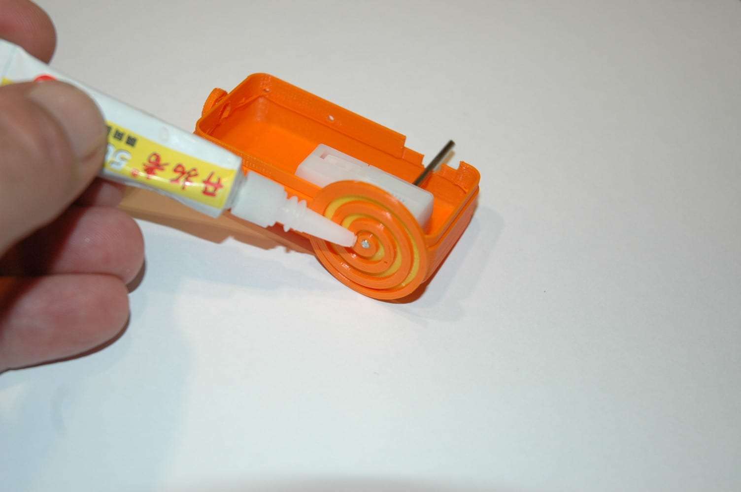
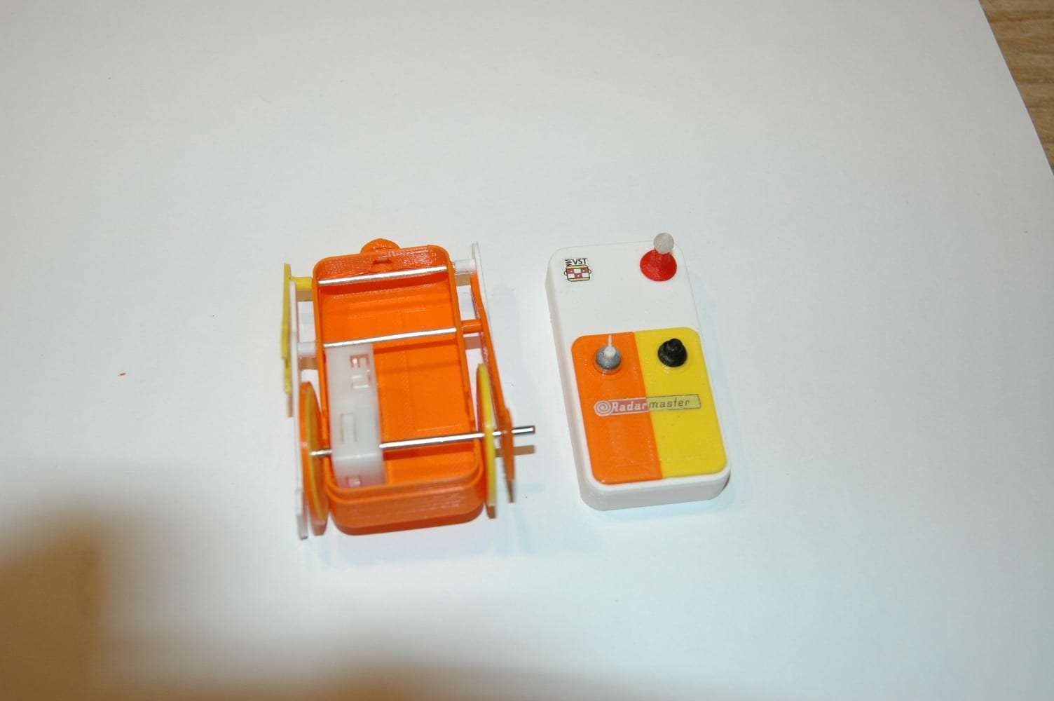
Step 1: Installing the mechanism to the bottom / backpart of the robots body.
( Pictures 1 – 7 )
– Make sure you glue the mechanism the correct way. The long rod sticks out to the right side of the body.
– Be carefull not to add glue into the mechanism as it will get stuck for sure.
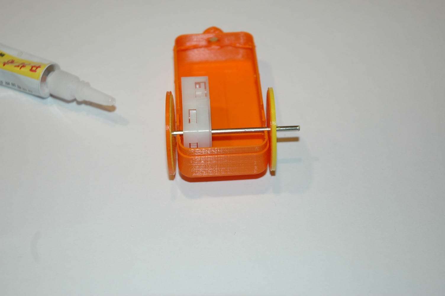
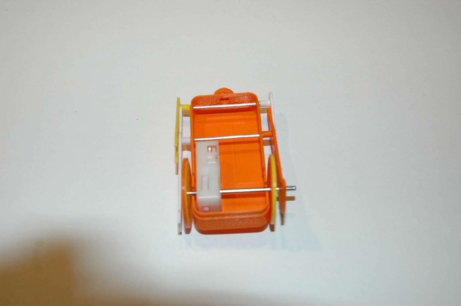
Step 2: Connecting the Wheels.
(Pictures 8 – 14)
– Glue the wheel parts together. the orange wheel goes with the yellow plate and vice versa.
– The hole for the orange wheel is tight so that it fit tight on the rod ( left side )
– The hole for the yellow wheel is slightly bigger so you can move it over the rod to the correct position.
– Both wheels need to be glued to the rod as shown in the pictures.
– Make sure the wheels are positioned straight and close to the body to leave enough room for the legs.
Step 3: Arms and Legs
(Pictures 15 -28)
– The arms and legs are static. They need to be glued to the body in the correct position. This is the hardest part of build. Made sure to note the colors left and right and pay special attention to picture 20 where glue is added to connect the arm and leg.
Also not the position of the leg and arms, forward and backward.
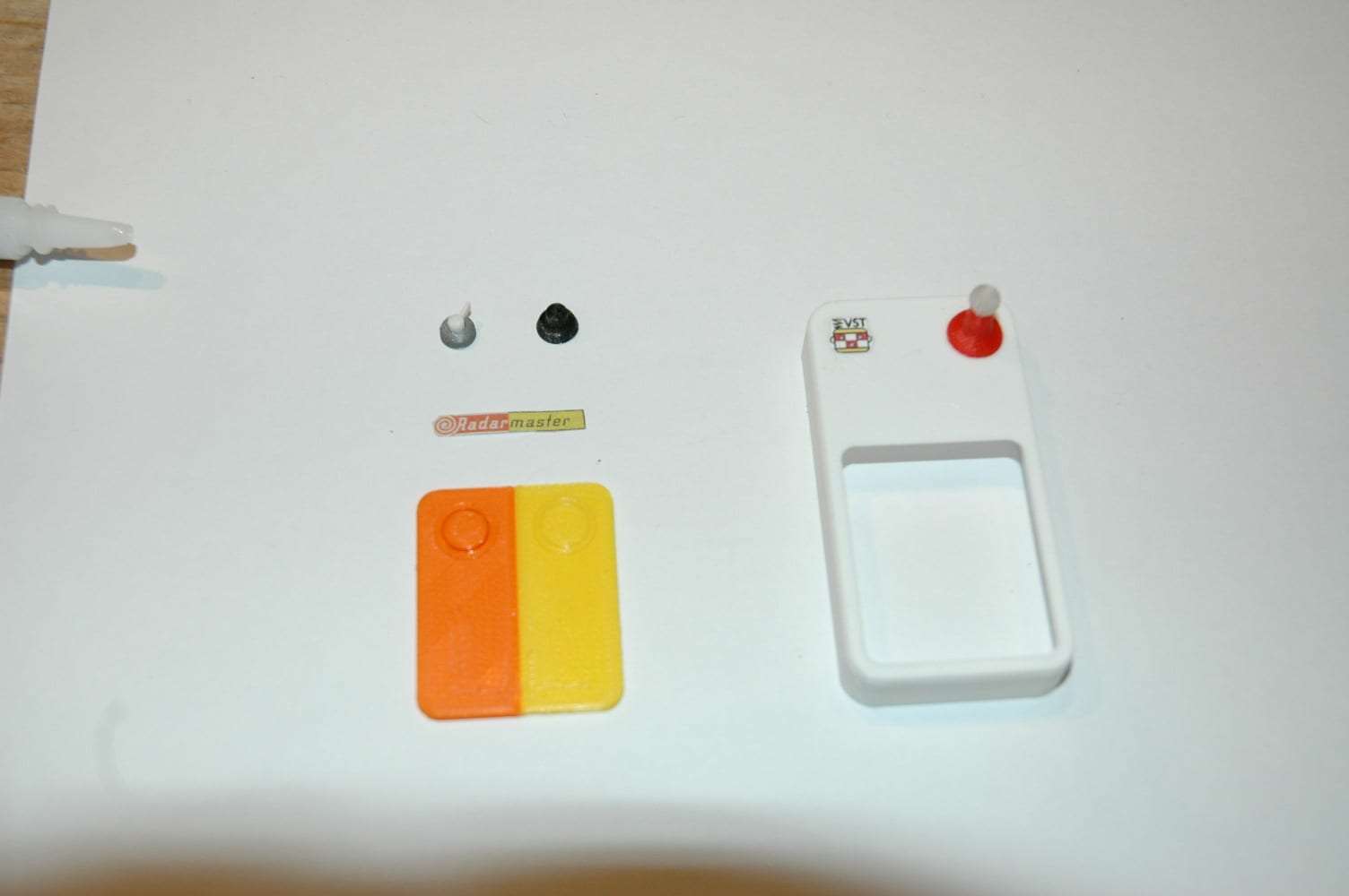
Step 4: Body Front Panel
(Pictures 29 – 47)
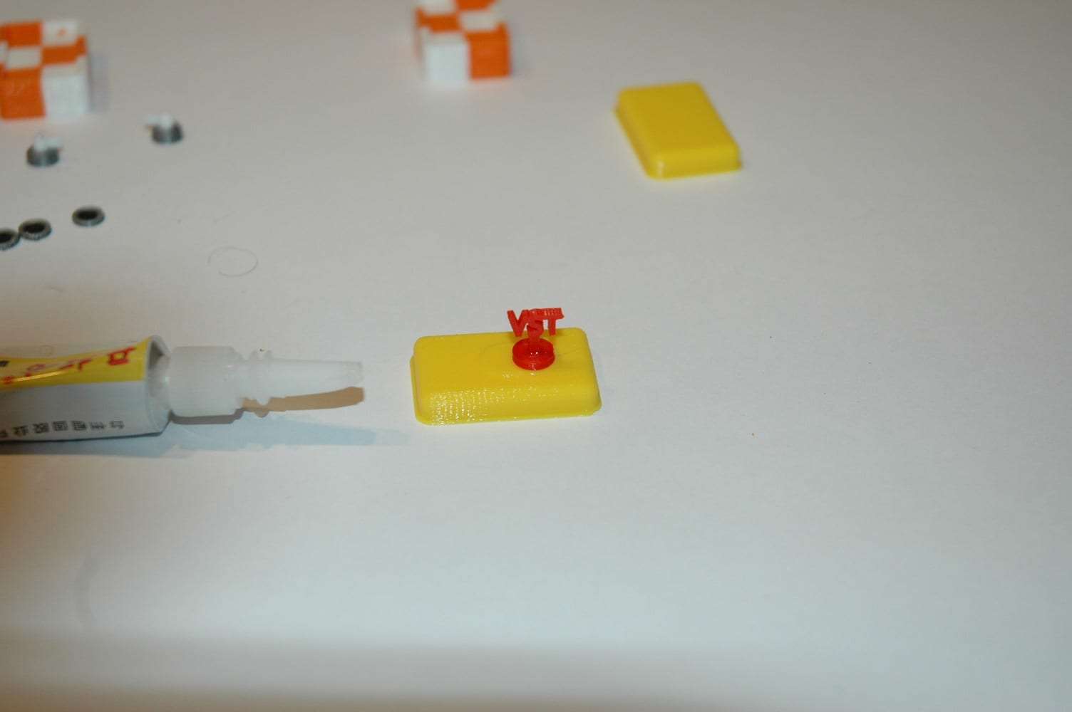
– The logo’s ( VST and Radar Master ) are made from paper. Cut them out precise by using scissors. The best way to glue these is by using a paper glue stick ( not provided in this set )
– when the front is completed you can snap it to the back part of the robots body.
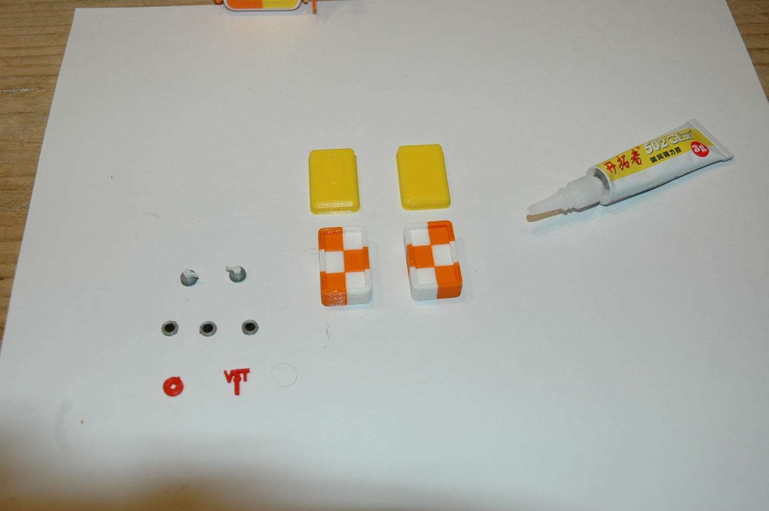
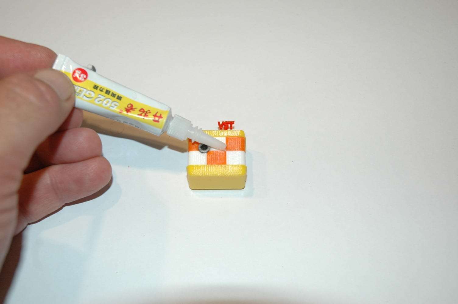
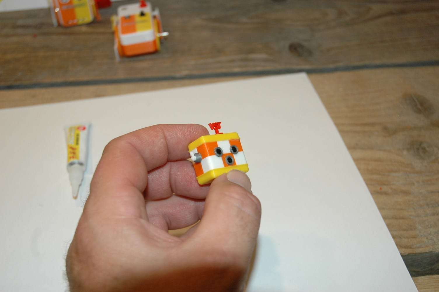
Step 5: Head
(Pictures 48 – 73)
– The pictures give a clear view of how the head is build up. Make sure you check the pattern of the white and orange block before you glue both the head parts together.
– The position of the eyes and nose is important so make sure you make that right.
The ears must be at the same height as the eyes.
Step 6: Wheel at the back
(Pictures 74 – 77)
– I have drawn a line at 1.7 mm from the bottom at the back of the orange body part. That is the mark where you have to glue the wheel. Test the postion before installing the wheel. The robot must tilt slightly backwards as shown in the pictures.
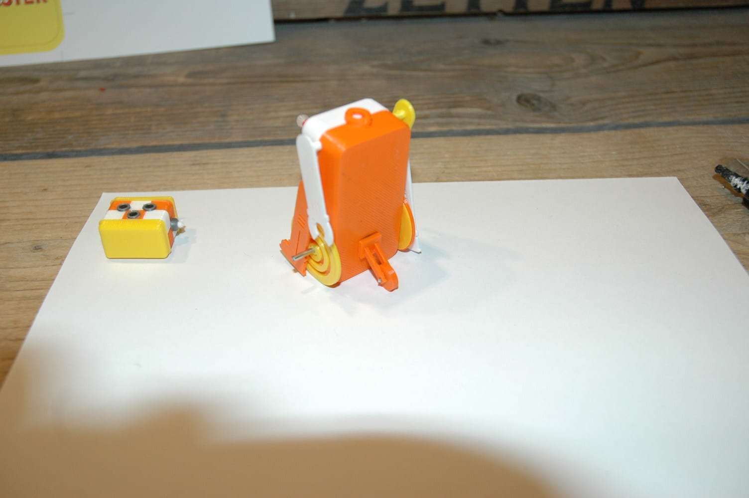
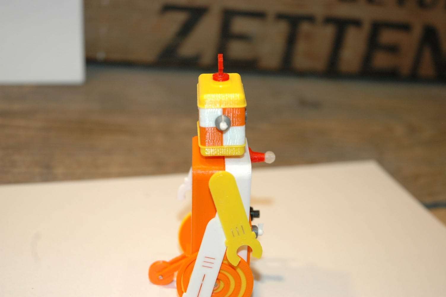
Step 7: The head
(Pictures 78 – 80)
Make sure the connetions are clean and slightly sanded. add glue all around the connection on the body and make sure the head is in the right position in the center. Check from frontview and sideview.
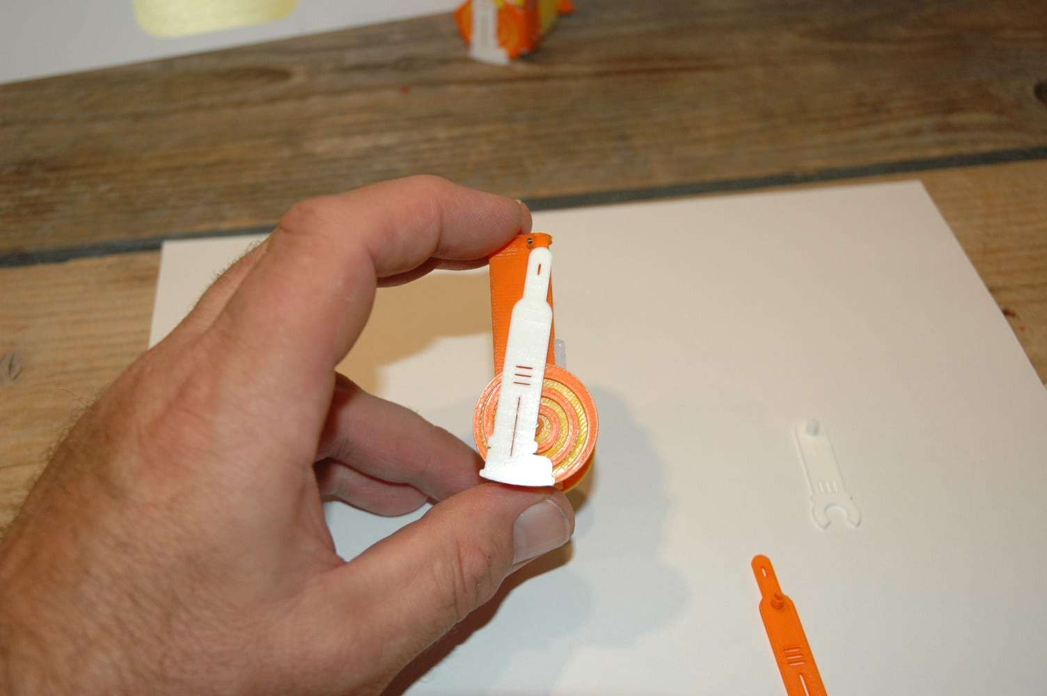
Step 8: Windup Key
(Pictures 81 – 83)
Sand the rod and add enough glue. Let it dry for at least 30 minutes.
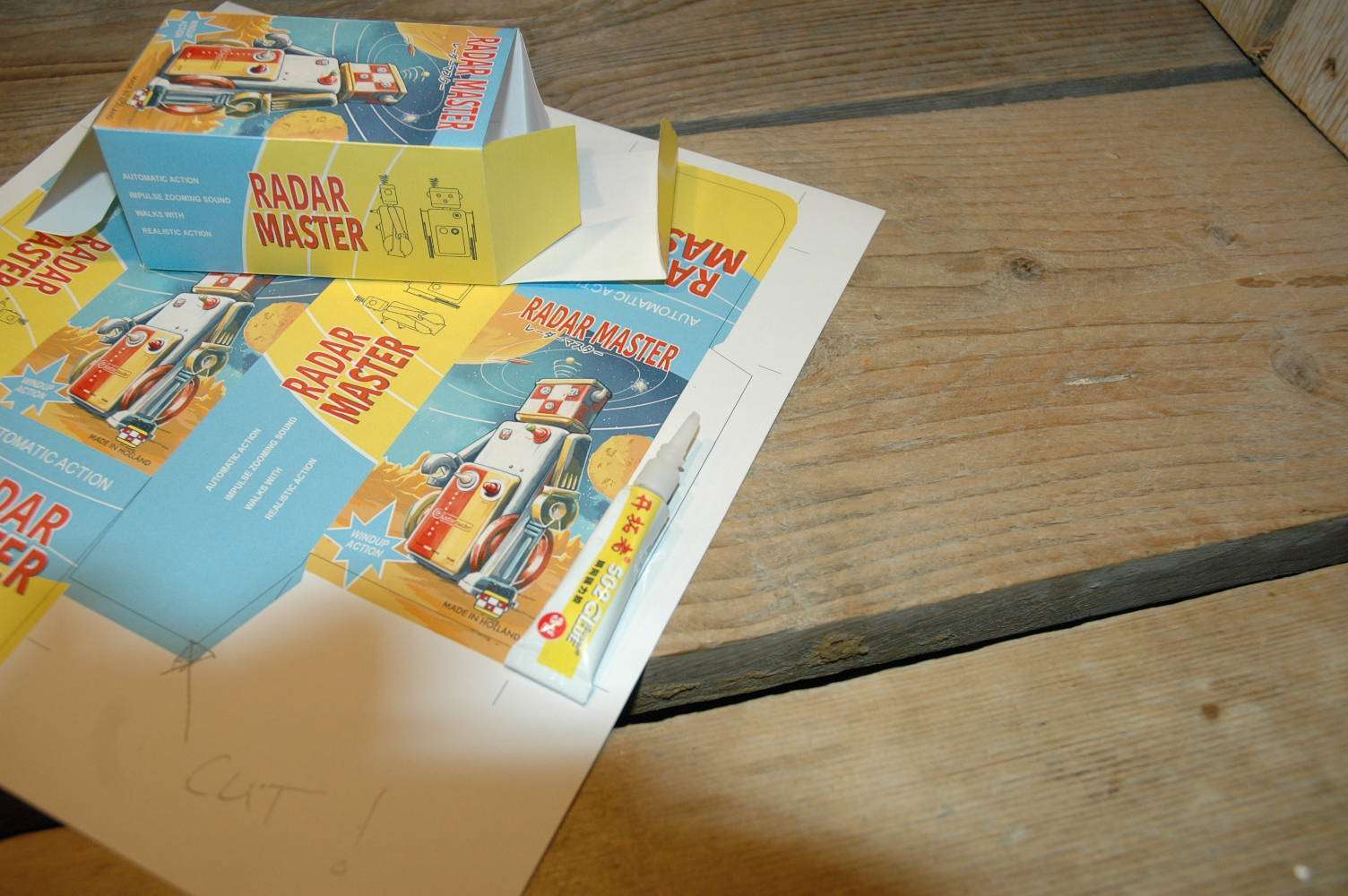
Step 9: The box.
(Pictures 84 – 90 )
– The box will get its strenght when its glued together. Make sure to cut exact on the marked line. Than fold precise and glue the box together.
Well Done ! and dont forget to sent me a picture of your finished robot to boogo.nl@gmail.com
Thank you, Marco